Flywheels
Storing rotational energy.

Background
The principle behind flywheel energy storage is to store energy in the form of rotational kinetic energy. The amount of energy stored depends upon the moment of inertia, I, of the rotating mass and its rotational velocity, $\omega$, as described by the Equation below.
$E = \frac{1}{2} I \omega^2$
The power rating is decided by the rating of the motor/generator. To charge the flywheel, useful energy (usually electrical, although direct mechanical drive systems are being explored) is used to increase the rotational speed of the flywheel- thus increasing its energy content. To discharge, kinetic energy is extracted from the flywheel (the flywheel is slowed) and converted into electricity via a generator (driven by the flywheel). Flywheels have long lifetimes (and require very little maintenance), can be very rapidly cycled and have good efficiency over short timescales, often quoted well in excess of 95%.
They can generally be separated into two categories. Low speed systems (up to around 6000rpm) and high speed systems (up to around 50,000 rpm). Low speed systems are a reasonably mature technology, are commercially available and indeed are extensively used in power quality applications. High speed systems are a technology more in research and development, and must be constructed of composite materials (to tolerate very high tensile stresses). They usually require low friction magnetic bearing setups and spin in a vacuum enclosure.
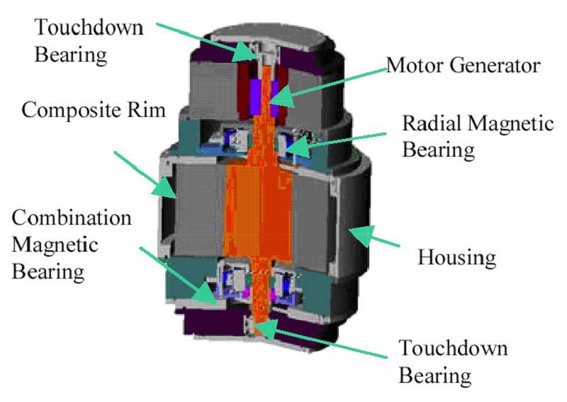
Figure: Depiction of a modern flywheel for energy storage
Flywheel characteristics and applications
Flywheels have many applications where a high power/short duration is required (e.g. 100 s of kW/10 s of seconds), in UPS, reactive power support, spinning reserve and voltage regulation. The most common application is to act as a power quality device to provide ride-through of interruptions up to 15 s long or to bridge the shift from one power source to another. Recent development has also produced flywheels capable of smoothing outputs from wind turbines. In the Azores, a 5kWh FESS dramatically improved system stability on a grid supplying 100,000 people, allowing a higher penetration of renewable energy and reducing diesel fuel usage. The system, installed by Powercorp of Australia, now smoothes wind power fluctuations allowing the operator to run the power station without keeping any diesel generators online. The 350 kW flywheel can respond to 100% fluctuations in demand in 4 milliseconds. Flywheels have also been used in energy recovery in electrically powered mass transit system.
They are really only suitable for applications which require high cycling, high power and small response times. Crucially they suffer from very high self discharge rates making them unsuitable for storage over timescales much longer than a few tens of minutes. There are several companies developing flywheel energy storage systems including Beacon Power, Pentadyne Power Corporation, Kinetech to name but a few.
Summary of characteristics
| Typical Capacity | Typical Power | Efficiency (%) | Storage Duration | $/kWh | $/kW | Lifespan | Cycling capacity |
| Up to 5MWh | Up to 20MW | 93 [1], 85 [2], 90-95 [3], 95 [4] | milliseconds - minutes | 1000-5000 [3], 1600 [4] | 200-350 [3], 600 [4] | 20 years | High |
Table: Flywheel characteristics
References
[1] EPRI, 2010. Electricity Energy Storage Technology Options