Compressed Air Energy Storage
Hybrid gas combustion and energy storage
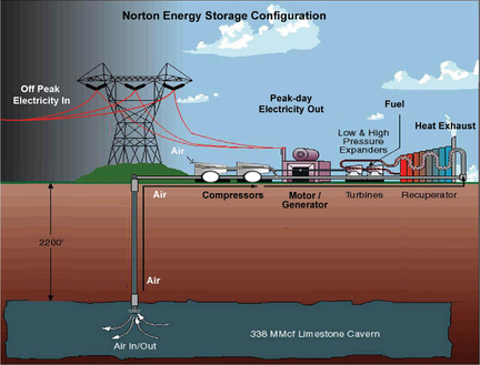
Figure 1: Schematic of diabatic CAES system.
Currently there are two commercial CAES plants worldwide; the Huntorf plant in Germany and the McIntosh plant in Alabama. Both of these use diabatic processes, wherein off-peak electricity is used to compress air, which is stored, and then when (peak) electricity is required the air is mixed with natural gas and combusted. The compression is staged with inter-cooling between each stage to cool the air. The expansion process is also staged, however there are fewer stages (typically just a high pressure exapnder and a low pressure expander). The compressed air is stored in large underground salt caverns. The Huntorf plant uses a 310,000m3 cavern at a depth of 600m with a pressure tolerance between 50 - 70 bar, converted from a solution mined salt dome. It runs on a daily charging cycle of 8 hours providing a peak output of 290MW for 2 hours. The McIntosh plant has a 538,000m3 salt cavern at a depth of 450m with a pressure tolerance between 45-76 bar. Originally it provided an output of 110MW for 26 hours but in 1998 two extra generators were added and its total capacity is now 226MW.
The existing CAES facilities are centralised storage facilities and the CAES design is generally considered to be well suited for centralised grid-scale storage systems. These facilities typically cycle on a daily basis. They often operate in part-load condition and their design allows CAES units to swing quickly from generation to compression modes. This flexibility means that they are well suited to ancillary services markets, providing frequency regulation. Their ability to operate on a (intra) daily cycle means that they are also useful for load-following/peak shaving. Although there are only two CAES plants in existence, and despite the fact that no new CAES plants have been built in excess of 20 years, these plants continue to operate viably in their respective markets.
CAES Performance Characteristics and Applications
The Huntorf plant, commissioned in 1978 to become the world's first CAES plant, uses 0.8kWh of electricity and 1.6kWh of gas to produce 1kWh of electricity. The McIntosh plant incorporates a recuperator to recover some of the leftover heat and uses 0.69kWh of electricity and 1.17kWh of gas to produce 1kWh of electricity [1]. Interestingly, in this type of process efficiency is not simply defined, since one can take the approach that the 0.69 kWh of electricity input for the McIntosh plant probably required 1.725 kWh of gas (assuming a gas turbine efficiency of 40%), implying an overall efficiency of 1/(1.17+1.725) = 34.5%. Alternatively, that 1.17 kWh of gas would have produced 0.468 kWh of electricity, and therefore the efficiency should be 1/(0.69+0.468) = 86.4%! Therefore, when analysing the performance of these hybrid energy-storage-gas-turbine systems exergy analysis is recommended.
As with PHS, CAES also requires favourable geography to provide the underground air storage caverns. There are many different underground cavern formations which can potentially be used for CAES, however storage in salt caverns is particularly appealing since these caverns are naturally airtight with little extra treatment. Aquifers and other underground caverns have also been proposed, however these are mainly experimental and thus the amount of extra work required to achieve satisfactory cavern performance is uncertain.
Crucially, since diabatic CAES is part energy storage and part natural gas combustion it has similar emissions to conventional gas turbines. There is recent interest in CAES variants that function without the need for natural gas. Adiabatic CAES, Isothermal CAES and absorption enhanced CAES are all new ideas in Research and Development.
Summary of characteristics
| Typical Capacity | Typical Power | Efficiency (%) | Storage Duration | $/kWh | $/kW | Lifespan | Cycling capacity |
| 500MWh – 2.5GWh | 50 – 300MW | n/a | Hours – days | 4-7 [1], 2-50 [2], 60 - 120 [3] | 300-600 [1], 400-800 [2], 1000-1250 [3] | 20-40 years | High |
Table: CAES characteristics
Costs
As with PHS, CAES costs are very site specific. The costs of mining a suitable underground cavern depend strongly on geology and whether existing caverns are already present. Above-ground air storage is also unproven in terms of expense. Turbine and compressor costs are also somewhat uncertain since turbines in particular must be specially designed, and therefore non-prototype costs may allow for significant reductions. It should be noted that the inlet pressure (45-76 bar) for the CAES high pressure turbine is much higher than the equivalent for a typical gas turbine (about 11 bar) so a typical gas turbine can only be used as the low pressure expander. The high pressure turbine at Huntorf is based on a small-intermediate steam turbine design. It is also worth noting that the Huntorf costs were considerably less than the equivalent cost in gas turbines in Germany at the same price date [5].
References
[1] B.I.N.E., 2007. Informationsdienst. Projekt info 05/07
[4] EPRI, 2010. Electricity Energy Storage Technology Options
[5] Ter-Gazarian, A., 2011. Energy Storage for Power Systems, s.l.: IET Power and Energy Series.